Surface Defect Detection Machine: How It Works and Why It Matters
Surface Defect Detection Machine: How It Works and Why It Matters
A surface defect detection machine is an automated inspection system that uses industrial cameras, controlled illumination, image-processing software, and, where appropriate, artificial intelligence (AI) to identify surface imperfections in manufactured components.
These systems help manufacturers detect defects such as scratches, cracks, dents, pits, stains, burrs, coating irregularities, and material contamination. Depending on the part geometry and inspection requirements, a system can inspect one surface or multiple sides of a component and automatically classify parts as acceptable or defective.
For high-volume manufacturing, automated surface inspection can reduce reliance on manual visual checks, improve inspection consistency, and help prevent defective products from reaching downstream processes or customers.
Openex Automation develops customized AI vision inspection systems for industrial components. The inspection configuration can be tailored to the part material, geometry, surface finish, target defect types, production rate, and required inspection coverage.
This guide explains how surface defect detection machines work, which defects they can identify, how AI improves inspection, and how manufacturers can select a suitable system.
Quick Answer: What Is a Surface Defect Detection Machine?
A surface defect detection machine is an optical inspection system that captures images of a product and analyzes them to identify surface conditions that do not meet predefined quality requirements.
A typical system combines:
- Industrial cameras and lenses to capture detailed images of the inspected part.
- Specialized lighting to make relevant defects visible.
- Machine vision software to process images and evaluate inspection criteria.
- AI-based defect recognition, when appropriate, to classify complex or variable surface anomalies.
- Automatic handling and sorting to separate accepted and rejected parts in an integrated inspection machine.
The system’s actual detection capability depends on defect size, contrast, surface reflectivity, material, part positioning, imaging resolution, lighting, and the inspection algorithm. Each application should be validated using representative samples and agreed acceptance criteria.
1. Why Surface Defect Detection Matters in Manufacturing
Surface defects can affect product appearance, assembly, sealing, corrosion resistance, fatigue performance, and overall product reliability. The consequences depend on the component, defect location, severity, and intended application.
For example, a scratch on a cosmetic plastic housing may affect appearance, while a crack on a load-bearing metal component may indicate a more serious structural concern. A defect on a rubber sealing surface may compromise sealing performance even if it is difficult to see under ordinary lighting.
Manual inspection and sampling checks may be insufficient when manufacturers produce large quantities of parts with consistent quality requirements.
Automated surface inspection helps manufacturers:
- Inspect production parts more consistently.
- Detect specified defects before shipment or assembly.
- Reduce dependence on repetitive manual visual checks.
- Separate defective parts automatically when connected to a sorting system.
- Record inspection results to support quality analysis, where data logging is configured.
- Identify recurring defect patterns that may indicate upstream process problems.
Importantly, automated optical inspection does not replace every form of quality testing. Internal cracks, subsurface defects, material composition, and other properties that are not optically observable may require non-destructive testing or specialized measurement methods.
2. Common Surface Defects Detected by Machine Vision
The first step in designing a surface defect detection machine is to define the defects that matter for the specific product.
Different defects create different visual characteristics. Some appear as dark or bright lines, while others appear as irregular regions, changes in texture, missing material, or variations in color.
2.1 Scratches and Abrasion Marks
Scratches are narrow marks that interrupt the original surface appearance. They may result from handling, machining, friction, transportation, or contact between components.
Typical inspection targets include:
- Linear scratches on metal surfaces.
- Abrasion marks on polished components.
- Scratches on coated or painted parts.
- Cosmetic scratches on plastic housings.
- Directional marks that differ from the expected surface finish.
Scratch detection can be challenging when the defect is shallow or when its reflectivity is similar to that of the surrounding material. Low-angle lighting, dark-field illumination, or multiple lighting directions may improve visibility, depending on the surface.
2.2 Cracks and Surface Fractures
Cracks can appear as fine lines, branching patterns, or irregular discontinuities.
Applications may include inspection of metal components, molded plastic parts, rubber components, and other products where surface cracking is a defined quality concern.
AI vision can help recognize complex crack patterns when representative training images are available. However, the ability to detect a crack depends on its visibility in the captured images. Subsurface or optically invisible cracks require an appropriate alternative inspection method.
2.3 Dents, Pits, and Surface Indentations
Dents and pits create localized changes in surface shape or appearance. They can occur during forming, machining, handling, or material processing.
Machine vision may identify these defects through changes in shading, contours, reflections, or texture.
For reflective metal parts, the lighting arrangement is especially important because the same indentation may appear very different under different illumination angles.
If defect depth must be measured quantitatively, a 3D vision system or another suitable metrology technology may be required.
2.4 Burrs and Excess Material
Burrs are unwanted material projections that can remain after machining, stamping, drilling, or cutting. Excess material can interfere with assembly or create sharp edges.
Vision inspection may detect visible burrs along edges, holes, slots, or machined features. The camera angle and image resolution must be appropriate for the burr size and location.
For very small burrs or defects hidden behind a component feature, additional camera views or specialized measurement methods may be necessary.
2.5 Coating, Plating, and Color Defects
Surface finishing processes can produce defects such as:
- Uneven coating coverage.
- Discoloration or color variation.
- Blisters and visible peeling.
- Stains and contamination.
- Localized coating damage.
- Oxidation or corrosion marks.
Color cameras, controlled illumination, and AI classification may be useful when defects are identified by color or appearance. Metallic and glossy coatings often require careful reflection control to distinguish genuine defects from normal lighting variations.
2.6 Foreign Particles and Surface Contamination
Dust, oil stains, fibers, metal particles, and other contaminants may affect product appearance or function.
The feasibility of detecting contamination depends on its size, color, contrast, location, and the material beneath it. Transparent, translucent, dark, or highly reflective surfaces can require specialized imaging arrangements.
Surface Defect Detection Reference Table
| Defect type | Typical visual feature | Possible inspection approach |
|---|---|---|
| Scratches | Linear marks or reflection changes | Directional lighting, multi-angle imaging, AI classification |
| Cracks | Fine lines or irregular discontinuities | High-resolution imaging, controlled lighting, AI recognition |
| Dents and pits | Localized shading or contour changes | Oblique lighting, contour analysis, or 3D measurement |
| Burrs | Protrusions along edges or holes | Edge imaging, silhouette analysis, multiple camera views |
| Coating defects | Color, texture, or coverage variation | Controlled illumination, color imaging, AI classification |
| Contamination | Foreign particles, stains, or unusual regions | Contrast-enhancing illumination and image classification |
These are possible approaches rather than guaranteed capabilities. The appropriate configuration must be confirmed for the target component and its acceptance criteria.
3. How Does a Surface Defect Detection Machine Work?
An automated surface inspection system combines image acquisition, defect analysis, and a quality decision. In a production environment, it may also include automatic feeding, part positioning, sorting, and data collection.
Step 1: Part Feeding and Positioning
The component is transferred into the inspection station through a suitable handling mechanism.
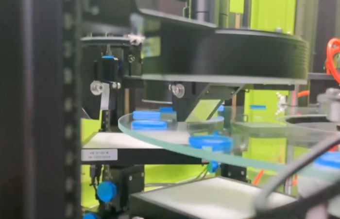
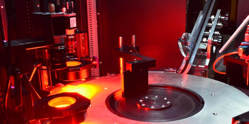
Depending on the product, this may involve a vibratory feeder, conveyor, indexing table, glass disc, rotary fixture, or customized handling mechanism.
Stable positioning matters because changes in orientation or distance can alter the captured image and reduce inspection consistency.
For components with complex geometry, the handling system must expose the surfaces that need to be inspected.
Step 2: Camera and Lens Selection
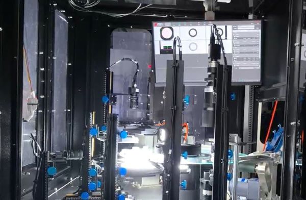
Industrial cameras capture images of the product. Lens selection determines the field of view, working distance, optical resolution, and perspective.
A system may use:
- Area-scan cameras for individual images of positioned parts.
- Line-scan cameras for continuous movement or suitable large-area applications.
- Multiple cameras for top, bottom, side, or oblique views.
- Specialized optical configurations for small features or reflective materials.
The required resolution should be calculated from the smallest relevant defect and the inspection tolerance. Camera megapixels alone do not determine whether a defect can be detected reliably.
Step 3: Lighting and Image Acquisition
Lighting is one of the most important factors in surface defect inspection.
A defect that is invisible under uniform frontal lighting may become obvious under low-angle illumination. Conversely, reflections from a polished metal surface can conceal a scratch or create a false defect signal.
Common lighting options include:
- Bright-field lighting: useful for general surface appearance and many dimensional features.
- Dark-field lighting: can emphasize scratches, edges, and surface discontinuities that scatter light.
- Dome lighting: can provide more diffuse illumination for reflective or curved surfaces.
- Backlighting: useful for silhouettes, holes, outlines, and certain dimensional checks.
- Coaxial lighting: useful for selected flat, reflective surfaces and imaging arrangements.
No single lighting type is ideal for every defect. Engineers typically evaluate multiple lighting configurations using actual good and defective samples.
Step 4: Image Processing and AI Defect Analysis
After image acquisition, the software analyzes the captured data against the inspection requirements.
Depending on the application, the system may use conventional machine vision, deep learning, or a combination of both.
Conventional algorithms are often effective for clearly defined features such as edges, dimensions, patterns, and predictable defects.
AI models can be useful when defects vary in shape, texture, appearance, or position and are difficult to describe using fixed image-processing rules.
The system may classify a part as acceptable, defective, or requiring additional review, depending on the configured decision logic.
Step 5: Quality Decision and Automatic Sorting
The inspection result is passed to the machine control system.
In an integrated inspection machine, the system can trigger an ejector, air jet, mechanical diverter, or other handling mechanism to separate defective parts from accepted parts.
Depending on the application, parts may be sorted into multiple categories, such as:
- Accepted products.
- Surface-defect rejects.
- Dimensional rejects.
- Parts requiring reinspection.
Correct synchronization between image acquisition, part tracking, and the sorting mechanism is essential to avoid rejecting the wrong component.
Step 6: Inspection Data and Process Improvement
Where data logging is included, the system can record inspection counts, defect categories, rejection rates, and selected images.
These records can help quality teams identify recurring defects, investigate production changes, and evaluate the effectiveness of corrective actions.
With appropriate integration, inspection results can also be transferred to a factory information system or manufacturing execution system (MES).
4. AI Surface Defect Detection vs. Traditional Machine Vision
Traditional machine vision and AI-based inspection are complementary technologies. The best solution depends on the defect characteristics, available image data, acceptable error rates, and production conditions.
Traditional machine vision usually relies on explicitly configured rules, thresholds, geometric measurements, or image features. Deep learning uses examples to learn visual patterns and can be helpful when acceptable and defective surfaces have complex or variable appearances.
| Comparison | Traditional machine vision | AI-based vision inspection |
|---|---|---|
| Basic approach | Explicit rules and image-processing operations | Learned patterns from representative image data |
| Geometric measurement | Well suited to clearly defined edges and features | Can complement measurement algorithms; measurement still requires validation |
| Repeatable, high-contrast defects | Often effective | Can also be effective |
| Complex surface appearance | May require extensive rule tuning | Can handle some complex visual variation |
| New defect types | May require new rules or thresholds | May require new examples, labeling, and model validation |
| Data requirements | Often relies on optical setup and engineered rules | Usually requires representative training and validation data |
| Explainability | Individual rules can be inspected directly | Model decisions may be less straightforward to interpret |
| Best selection criterion | Predictable defects and clearly defined measurements | Variable defect patterns that benefit from learned visual features |
AI does not automatically guarantee higher accuracy. Performance depends on image quality, training data, defect variability, model configuration, and validation under real production conditions.
A hybrid approach can be particularly effective: use conventional vision for dimensional measurements and deterministic geometry checks, and AI for complex surface classification.
5. How to Inspect Reflective Metal Surfaces
Reflective materials are among the most challenging targets for optical defect detection.
Polished steel, aluminum, plated fasteners, and machined metal parts can reflect surrounding objects and light sources. As a result, a scratch may appear bright under one lighting angle and nearly disappear under another.
A reliable inspection design should consider the following factors.
Control the Lighting Environment
Use controlled illumination to reduce unwanted reflections and make the defect of interest stand out.
Depending on the surface, engineers may evaluate low-angle, diffuse, coaxial, or multi-directional lighting.
Capture Multiple Views When Necessary
A single camera may not reveal defects on every side of a curved or complex component.
Additional cameras or part rotation can improve coverage, provided that the system maintains suitable resolution and inspection time.
Separate Normal Surface Texture from Actual Defects
Machining marks, brushing patterns, grain, and normal texture can resemble scratches.
AI models can help distinguish specified defects from acceptable variations when the training and validation samples represent real production conditions.
Validate Across Real Production Variation
Tests should include parts from different production batches, expected surface finishes, and normal process variation.
This helps determine whether the system can detect the target defects without rejecting an unacceptable proportion of good parts.
6. Which Industries Use Surface Defect Detection Machines?
Surface inspection is relevant wherever appearance, material integrity, or surface condition forms part of a product’s acceptance criteria.
Automotive Components
Metal and plastic automotive parts may require inspection for scratches, cracks, dents, burrs, molding defects, and coating irregularities.
Applications can include fasteners, piston pins, connectors, clips, housings, and other precision components.
Explore Openex Automotive Parts Inspection Machines.
Fasteners and Metal Hardware
Screws, bolts, nuts, and special fasteners may need checks for head damage, scratches, cracks, plating issues, incomplete features, and dimensional deviations.
Surface inspection can be combined with thread and dimensional checks in a suitably configured system.
Explore the Openex Fastener Inspection Machine.
Rubber and Plastic Components
Rubber seals, O-rings, molded plastic components, and composite parts may require detection of cracks, cuts, flash, contamination, discoloration, or missing material.
Flexible materials can deform during handling, so part presentation and inspection criteria must be designed accordingly.
Explore Openex Rubber and Plastic Parts Inspection.
Electronics and Semiconductor Components
Electronic components may require inspection for scratches, cracks, contamination, chipping, surface discoloration, and other visible defects.
Small features and reflective surfaces can require specialized optics, controlled lighting, and carefully validated image acquisition.
Explore Openex Semiconductor Inspection Machines.
7. Surface Defect Detection vs. Dimensional Inspection
Surface defect detection and dimensional inspection are related but different tasks.
Surface defect detection determines whether a component has unwanted visual features, such as a scratch, crack, stain, or pit.
Dimensional inspection measures geometric properties such as length, width, diameter, hole position, contour, or thickness and compares the measurements with specified tolerances.
A combined inspection system can perform both tasks when the camera arrangement, optics, calibration, software, and handling mechanism support the requirements.
For example, an automotive metal component may need to pass both a surface-quality check for scratches and a dimensional check for outer diameter.
However, surface defect detection alone does not establish dimensional accuracy, and a dimensional measurement system does not necessarily detect every surface anomaly.
For applications requiring both capabilities, define the dimensional tolerances and surface acceptance criteria separately before selecting the inspection configuration.
8. How to Choose the Right Surface Defect Detection Machine
Selecting a machine should begin with the inspection requirement rather than the camera or AI technology alone.
1. Define the Target Defects
List each defect type and specify its minimum relevant size, location, severity, and acceptance criteria.
If possible, provide examples of acceptable and defective parts.
2. Identify the Part Material and Surface Finish
Metal, plastic, rubber, ceramic, glass, and coated materials interact with light differently.
The inspection design should account for reflectivity, transparency, color, texture, and expected surface variation.
3. Determine Required Inspection Coverage
Identify which surfaces must be inspected: top, bottom, sides, edges, holes, grooves, or other features.
The machine may require multiple cameras, part rotation, special fixtures, or additional inspection stations.
4. Set the Production Throughput
Define the required parts per minute or parts per hour, including normal production variation and any downstream handling constraints.
Inspection speed should be validated using the complete system rather than the camera’s theoretical acquisition rate alone.
5. Establish Detection and False-Reject Criteria
Define acceptable detection performance and the maximum tolerable false-reject rate.
A false reject occurs when a good part is incorrectly classified as defective. A missed defect occurs when a defective part is incorrectly accepted.
Both should be measured using representative samples and agreed test procedures.
6. Evaluate Integration Requirements
Determine whether the system needs automatic feeding, sorting, recipe changeover, inspection records, barcode reading, or MES connectivity.
Integration requirements affect machine layout, control design, cycle time, and total project cost.
7. Request a Sample-Based Feasibility Test
A practical evaluation should use real components, representative defects, and agreed acceptance criteria.
The evaluation should document:
- Defects that can be detected.
- Inspection surfaces and blind spots.
- Achievable throughput under the proposed configuration.
- Detection performance and false rejects on the test set.
- Measurement capability, where applicable.
- Handling, sorting, and integration requirements.
This is a more reliable basis for selecting equipment than comparing advertised camera resolution or AI features alone.
9. What Determines the Cost of a Surface Defect Detection Machine?
The cost of an automated inspection machine depends on the application and the degree of customization required.
Important cost factors include:
- Part geometry and material.
- Number and type of defects to detect.
- Camera, lens, and lighting configuration.
- Number of inspection views or stations.
- Required production throughput.
- AI model development and validation.
- Feeding and automatic sorting mechanisms.
- Traceability and factory-system integration.
- Installation, commissioning, and ongoing support.
A system inspecting one visible surface of a stable component can have very different requirements from a machine inspecting every side of a small, reflective component at high speed.
For a meaningful proposal, provide the part drawing, sample images, target defects, production rate, and required inspection coverage.
10. Frequently Asked Questions
What is a surface defect detection machine?
A surface defect detection machine is an automated optical inspection system that uses cameras, lighting, and image-analysis software to identify surface imperfections such as scratches, cracks, dents, pits, stains, and coating defects.
Can AI detect scratches and cracks on metal parts?
AI can classify visible scratches and cracks when the optical system captures sufficient information and the model has been appropriately trained and validated. Detectability depends on defect size, contrast, surface finish, lighting, and camera resolution. Subsurface defects may require other inspection methods.
What is the difference between AI inspection and traditional machine vision?
Traditional machine vision commonly uses configured rules, thresholds, and geometric algorithms. AI inspection learns visual patterns from example data and can be useful for complex or variable defect appearances. Both approaches can be combined in one inspection system.
Can one machine detect both surface defects and dimensional errors?
Yes, if the machine is designed for both tasks. The required cameras, optics, lighting, calibration, and software depend on the dimensions and defect types being inspected.
Can a surface defect detection machine inspect 100% of production?
A properly integrated inline system can be designed to inspect every part passing through it. Achieving complete coverage and reliable performance depends on handling stability, production speed, optical access, and validated inspection performance.
How do you inspect scratches on reflective metal?
Reflective metal often requires controlled lighting, suitable camera angles, and careful management of glare. Depending on the part, engineers may evaluate low-angle, diffuse, coaxial, or multi-directional illumination. Actual samples should be used to validate the setup.
How can I determine whether my part is suitable for AI surface inspection?
Provide representative good parts, defective samples if available, drawings, defect descriptions, required throughput, and inspection criteria. An engineering feasibility test can help establish whether the required defects are optically detectable and which configuration is appropriate.
11. Request a Customized Surface Defect Inspection Solution
Every component presents a different inspection challenge. A lighting arrangement that reveals scratches on polished steel may not work for black rubber, transparent plastic, or textured molded parts.
Openex Automation develops customized machine vision and AI inspection systems based on component geometry, material, surface condition, defect characteristics, production requirements, and automation needs.
Our engineering team can help evaluate:
- Whether your target defects are optically detectable.
- Which camera and lighting configuration is appropriate.
- Whether AI, conventional vision, or a hybrid approach is suitable.
- How many inspection views are required.
- How inspection and sorting can fit into your production process.
Want to evaluate your component? Send us your part drawing, photographs, defect samples, and target production rate.
Contact Openex Automation to discuss your surface inspection requirements and request a customized technical proposal.
Email: sales-auto@openex.com.cn
Phone: +86 186 5928 0806